Compatibility:
- U3-LV
- U3-HV
- U6
- U6-Pro
- UE9
- UE9-Pro
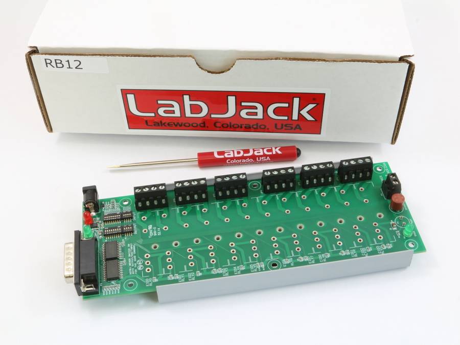
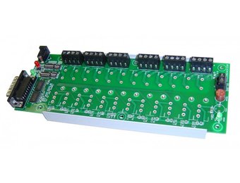
The RB12 Provides a convenient interface to industry standard I / O modules, allo wing electricians, engineers, and other Qualified Individuals, to interface a Labjack with high voltages / currents. Logic buffers are used to providence the 10-15 mA typical needed for each I / O module, So THAT the current is provided by the 5 volt supply rather than the logic control lines.
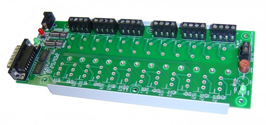
The RB12 relay board connects to the DB15 connector on the Labjack U3 / U6 / UE9, using the EIO / CIO digital I / O lines to control or read industry standard digital I / O modules. The RB12 is designed to connect directly to the Labjack, but ook can connect via a 15-line 1: 1 male-female cable (not included or required)
The RB12 PCB is mounted to a piece of Snap Track. The Snap Track is DIN rail mountable using Tyco part #TKAD (not included).
The green LED on the RB12 is directly powered by the 5 volt supply (Vs) from the Labjack, so it Should be lit whenever the RB12 is connected to a powered Labjack. The red LED is powered directly by the external power supply (not included or required).
Power Supply
The RB12 can be powered from the Labjack through the DB15, or from an external 5-volt supply on power jack P1. If both the Labjack and external supply are connected at the same time (both green and red LEDs on), the external power supply willprovide. In most cases, the RB12 can simply be powered by the Labjack, but there are various Reasons Why powering from an external supply, rather than the Labjack, might be desirable. For example, most I / O modules use 10-15 mA, and osmanthus 12 of them would use 120- 150 mA total. In most cases a Labjack can providence this power without problem, but if 12 of the 70G-IDC5S module (iSupply = 41 mA) were used, the total power required by the RB12 could be about 500 mA-which is a problem for most LabJacks.
If an external supply is used, it shouldering be regulated with a nominal voltage of 5.0 volts. This is gene rally provided by a wall-wart or wall-type transformer or supply. A supply capable of 500 mA or more is recommended. The power jack connector is 2.1x 5.5mm, center positive.
Towards the bottom of the RB12 is a two-position screw terminal (P3) with GND and US This is designed as an output connection to providence the user access to the 5 volt supply.
If the RB12 is powered by an external supply, always maintain valid control signals (EIO / CIO) for all output I / O modules. For instance, if the RB12 is powered by a wall-wart, but there's nothing connected to the DB15, the state of output modules is undefined and might vary, but is likely to be enabled.
Output / Input Configuration
The RB12 can be used with output or input types or digital I / O modules. There are four banks of DIP switches used to configure Whether each of the 12 channels is for output or input. When the switches in the S1 and S2 banks are put in the ON position, Those lines are configured for output I / O modules. When the switches in the S3 and S4 banks are put in the ON position, Those lines are configured for input I / O modules. To avoid uncertain behavior, do not turn on output and input switches for the same line at the same time.
All output modules are controlled with negative logic. That Means the Labjack control line (EIO / CIO) must be driven to output-low to enable the I / O module. With the control line driven to output high, or set to input and pulled high, the I / O module will be disabled. Input modules use normal logic, Such That a true input will cause the Labjack EIO / CIO line to read high.
I / O Modules
Specifically for more information about the various I / O modules, see the documentation from the manufacturer. Such is OPTO22 One manufacturer, and as of this writing, the OPTO22 "Generation 4 Digital I / O Family Data Book" is dated April 2004 and available at the Following URL: http://www.opto22.com/documents/0727_G4_Digital_IO_Data_Book. pdf
Pages 33-49 of this databook cover the available modules-including typical wiring diagrams. The Following table maps the I / O modules, pin numbers 1-5 (as shown in the OPTO22 databook) to Their respective RB12 connections:
| I / O Module | RB12 |
| 1 | Rn + screw terminal |
| 2 | Rn screw terminal |
| 3 | Vs (~ 5 volts) |
| 4 | 4.7 kΩ pull-up to Vs and Eion / Cion (buffered output for direct connection for input) |
| 5 | GND |
When configured for output, the control line (EIO / CIO) from the Labjack connects to a logic buffer-which then connects to pin 4 of the I / O module. When the control line is high, the output buffer is in a high-impedance state. When the control line is low, the buffer output is connected to ground with the ability to sink up to 24 mA.
When configured for input, the control line (EIO / CIO) from the Labjack connects directly to pin 4 of the I / O module.
The RB12 includes a spare fuse. There is ook a fuse tester socket where if a fuse is installed the "GOOD" green LED will light. The spare fuse holder and tester on the RB12 are designed for the TR5 fuse used by OPTO22 (Digikey part number WK3062BK).